AFM Tip and Resolution: Why Your Probe Matters
Atomic Force Microscopy can, in principle, resolve features down to the atomic scale. In practice, what you actually resolve depends on the probe mounted in your instrument. Understanding this relationship is the first step toward getting the most out of every scan.
In this article we will focus on the effects of tip geometry on idealized hard samples. In practice, factors such as mechanical compliance of the sample, surface hydration, and long-range interactions (e.g., van der Waals forces) can limit the resolution relative to that predicted by the simple geometric arguments presented here. Other factors related to the sample, operating mode, and imaging environment may also contribute to this reduction. Additionally, as with any digital instrument, data acquisition parameters and post-processing can also limit the resolution.
AFM resolution is usefully divided into two components. Lateral resolution describes how well the instrument can distinguish two nearby features in the X–Y plane. Vertical resolution describes sensitivity to height differences in Z.
Vertical resolution is largely an instrument property — modern AFMs routinely achieve sub-ångström noise floors in the Z axis, determined by thermal noise, detector sensitivity, and vibration isolation. Lateral resolution nowadays is almost entirely a probe property. The two are governed by different physics, which is why a high-quality instrument paired with a poor probe still delivers disappointing images. Bad probe quality or a broken tip is also closely related to the presence of other artifacts in the image, such as doubled features, or repeating spurious shapes – we have covered some of these artifacts in a separate article.
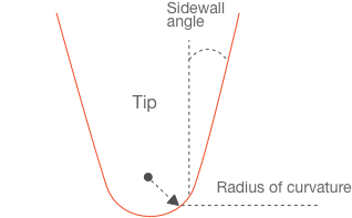
Figure 1 Tip geometry - as shown in our article on AFM Tip Shape Effects
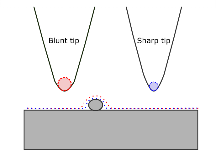
Figure 2 Effect of tip radius. The trajectory of a blunt tip (red) and a sharper tip (blue) on a surface with a protruding particle.
When an AFM tip scans across a surface the image is a mathematical convolution of the surface topography with the three-dimensional shape of the tip rather than the actual surface. Edges, particles and trenches in the image are broadened or distorted by the finite geometry of the AFM probe.
The most important parameter is the AFM tip radius. A sharp tip with a 1–2 nm radius can follow fine surface features faithfully. A blunt tip with a 20–30 nm radius smooths those same features into rounded, widened artefacts. The sharpness of the AFM tip sets a hard ceiling on lateral resolution that no amount of signal averaging or post-processing can overcome.
While the exact quantitative dependency is complex, and requires detailed knowledge of the AFM probe geometry, we can approximate the effect of tip radius on measuring protrusions with the following formula.
For a spherical AFM tip of radius R scanning over a spherical particle of radius r, the apparent lateral width W of the particle is:
W = 2√(2Rh)
where h is the true height of the feature. This assumes R >> h. Notably, broadening scales with √R, so halving the AFM tip radius from 20 nm to 10 nm reduces broadening by ~30%, while going from 20 nm to 2 nm radius reduces it by ~70%.
Aspect ratio and closely related tip half-angle matters just as much when imaging high-relief samples — deep trenches in semiconductor structures, tall nanoparticles, or biological filaments. A low-aspect-ratio tip cannot reach the bottom of a narrow feature; instead it "bottoms out" on the sidewalls, producing an artificially shallow, rounded measurement. High-aspect-ratio AFM probes — with slender, needle-like geometries — are specifically designed for these situations.
The half-angle can be used to estimate the trench resolution of the probe. Assuming the trench dimensions are much greater than the tip radius, the minimum resolvable trench width at depth d is:
Wmin = 2d · tan(θ)
A tip with a 20° half-angle imaging a 100 nm deep trench will produce an apparent width floor of ~73 nm as long as the above assumption about radius still holds. This is why high-aspect-ratio AFM probes (small θ) are essential for deep-feature metrology. For measuring deep trenches, specialist high-aspect ratio probes product lines exist. Additionally, some tips have different angles depending on scan direction, as we have covered in another article.
AFM tip wear is the practical limitation of even the sharpest AFM probes. Silicon AFM tips are hard but brittle; brief accidental contact with a hard and/or rough surface can increase the effective AFM tip radius from ~5 nm to many orders of magnitude larger. The image degrades gradually or catastrophically, and the change is not always obvious without scanning a known reference structure. Building a habit of checking AFM tip sharpness — using a calibration grating or sharp nanoparticle standard — saves enormous amounts of wasted experiment time.
The hard limit on resolution in X is often cited as:
δx ≈ 2√(2Rznoise)
Where znoise is the thermal noise of the AFM system’s piezo scanner in the z direction. This motion in the Z axis indirectly influences the acquired X and Y dimensions of the AFM image. The expression is essentially the same as for the minimum width above, but this time we substitute the z axis noise, instead of the height.
To conclude, tip quality is instrumental to a good image, and if poor, even sophisticated modern systems would struggle to adapt to it. However, when scanning unknown surfaces, there could be no objective indicator of AFM probe quality, necessitating the disciplined use of calibration standards to maximize the informational value of AFM images.