AFM Tip Shape Effects
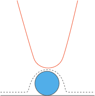
Atomic Force Microscopy (AFM) is a measurement technique that is capable of very high magnification imaging. Unlike other techniques, AFM resolution is not limited by photon or electron wavelengths. AFM uses a super-sharp AFM tip for mechanical scanning of sample surfaces in a similar fashion to a blind man who reads Braille code with his fingers.
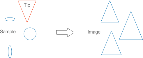
Images obtained by scanning a sample with an AFM tip are strongly dependent on the AFM tip geometry. AFM scans are a result of the convolution of the AFM tip and the surface. The smaller the surface features compared to the AFM tip dimensions, the less accurate the sample image on the computer screen.
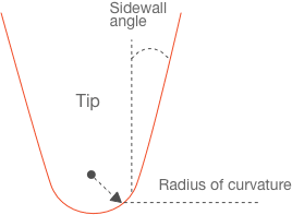
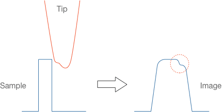
The two most important AFM tip related factors that affect the quality of the AFM scans are the apex radius of curvature and the sidewall angles (Fig. 1). The AFM tip radius is the real limitation of the ultimate resolution that an AFM measurement can yield, while the AFM tip sidewall angles affect the accurate imaging of steep slopes.
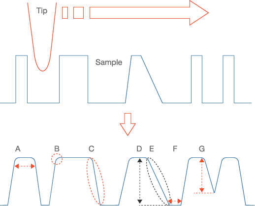
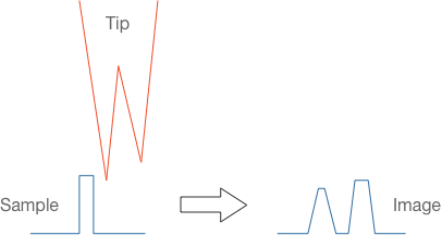
How does the AFM image compare to the real surface topography? The main effects of AFM tip geometry are shown in Fig. 2 and explained below.
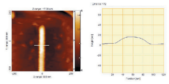
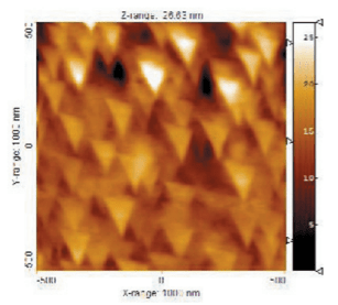
As frictional wear dulls the AFM tip progressively, the above described effects become more and more pronounced. After a certain point, the contact area of the AFM tip with the surface is so large that it dominates the shape of small features and all of them appear to have very similar shape and the same orientation (Fig. 5, Fig. 6). This shape is actually the AFM tip apex shape rotated by 180 degrees and its geometry depends on the cross section of the AFM tip pyramid.
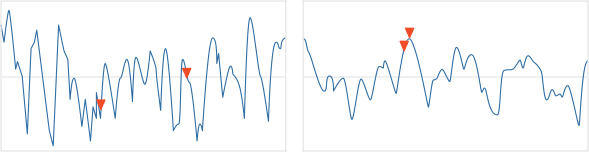
When the AFM tip is broken, for example as a result of improper engage with the surface, and there are additional non-idealities on the apex, they can show up as fake feature details in the AFM image (Fig. 7, Fig. 8).
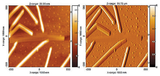
The artifacts can be even more severe. When the pyramid has more than 1 AFM tip that can contact the sample surface during scanning, multiplication of feature images occurs (Fig. 9, Fig. 10).
Some AFM tip shape effects such as shape distortions or artificial details are not hard to detect. They are present throughout the scanned image in an identically repeatable and clearly recognizable pattern. Other effects are more subtle and users can not immediately identify them just by a quick look at the computer screen. Therefore, good judgment must be used when measuring nanoscale distances or interpreting nanoscale feature shapes. By knowing the peculiarities of AFM measurements imposed by the AFM tip shape, it is nevertheless possible to extract useful information from the AFM scans or recognize a false measurement that needs to be redone.

Understanding AFM tip shape and its effects on AFM measurements is essential for performing successful AFM analysis.
Choosing the right AFM probes is critical for achieving good AFM measurement results. AFM tip sharpness is directly related to the maximum achievable resolution
All image distortions caused by dull or broken AFM tips can also appear as a result of particles sticking to the AFM tip and acting as an AFM tip apex. Many AFM systems operate outside of clean-room facilities. Keeping the working space, probes and samples clean will reduce particle contamination and improve the quality of the AFM scans.