A thick and short AFM cantilever usually has a high resonance frequency and a high force constant*. Such an AFM cantilever is suitable for non-contact or intermittent contact mode AFM operation.
» Browse all AFM probes with tapping mode AFM cantilevers
Long and thin AFM cantilevers have a low resonance frequency and a low force constant*. These AFM Cantilevers are suitable for contact mode AFM operation.
» Browse all AFM probes with contact mode AFM cantilevers
AFM cantilevers with an intermediate length and an intermediate thickness have an intermediate resonance frequency and an intermediate force constant. These AFM cantilevers are suitable for force modulation mode AFM operation.
» Browse all AFM probes with force modulation AFM cantilevers
There are AFM cantilevers with specific geometries for specific requirements. For example, certain AFM systems require » long tapping mode AFM cantilevers, while other AFM systems require » short contact mode AFM cantilevers.
There is no common definition on the exact force constant values of stiff (or hard) and soft AFM cantilevers. Our own definition of these terms is the following:
An AFM cantilever with force constant above 40 N/m is referred to as a ‘stiff’ AFM cantilever. Such an AFM cantilever allows maximum scanning speeds in tapping/non-contact mode AFM measurements.
An AFM cantilever with force constant in the range 3-15 N/m is referred to as an ‘intermediately stiff’ AFM cantilever. Such an AFM cantilever is usually preferred for soft intermittent contact mode AFM measurements with reduced tip-sample interaction (5-15 N/m) and for force modulation measurements (3 N/m).
An AFM cantilever with a force constant below 1 N/m is referred to as a ‘soft’ AFM cantilever. Such an AFM cantilever allows high sensitivity contact mode AFM measurements.
For more information on AFM cantilevers, please contact us.
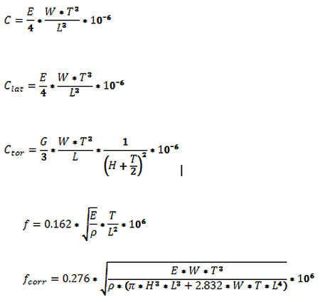
* We are referring to the normal force constant of the AFM cantilever. For more information about the different AFM cantilever force constants, check the next chapter.The normal resonance frequency (or simply the resonance frequency) f of an AFM cantilever refers to the resonance frequency for small amplitude oscillations in the direction normal to the sample facing surface of the AFM cantilever. This parameter neglects the mass of the tip.
The corrected resonance frequency fcorr of an AFM cantilever takes the AFM tip mass into account. Here, the AFM tip is modeled as a cone with height H and a base diameter H.
The normal force constant (or simply the force constant) C of an AFM cantilever is the ratio of the applied force from the top or the bottom side at the free cantilever end to the free end’s displacement for small displacements (Fig. 1). This force constant is most relevant for determining the tip-sample interaction during the majority of AFM operation modes.
The lateral force constant Clat of an AFM cantilever is the ratio of the applied force from the side at the free end of the AFM cantilever to its displacement for small displacements (Fig. 2).
The torsional force constant Ctor of an AFM cantilever is the ratio of the applied lateral force at the AFM tip to the lateral displacement of the AFM tip for small displacements (Fig. 3).

The calculator below calculates important parameters of silicon AFM cantilevers based on their geometric dimensions.
f [kHz] – resonance frequency of the AFM cantilever (neglecting tip mass)
fcorr [kHz] – resonance frequency of the AFM cantilever taking tip mass into account
C [N/m] – (normal) force constant of the AFM cantilever
Clat [N/m] – lateral force constant of the AFM cantilever
Ctor [N/m] – torsional force constant of the AFM cantilever
T [µm] – AFM cantilever thickness
W [µm] – AFM cantilever width
L [µm] – AFM cantilever length
H [µm] – AFM tip height
ρ = 2.33g/cm3 = 2330kg/m3 - density of silicon
E = 1.69*1011 N/m2 - modulus of elasticity / Young’s modulus in the <110> direction of silicon
G = 0.5*1011 N/m2 modulus of rigidity / modulus of elasticity in shear of silicon
The calculator calculates the resonance frequencies and the force constants according to the following formulas: