ScanAsyst®** AFM Probes
ScanAsyst®** is an off resonance Atomic Force Microscopy (AFM) scan mode for mainly topography imaging with automatic image parameter control and adjustment. Off resonance AFM mode means that the AFM probes and AFM cantilevers used while acquiring the AFM image don’t operate on or close to their Eigenfrequency – therefore ScanAsyst®** as well as Peak Force Tapping™** are called an off-resonance AFM operation mode.
This by Bruker Corporation so-called auto-optimization ScanAsyst®** technique is based on the Peak Force Tapping™** mode which got introduced by Bruker Corp. in 2010. Peak Force Tapping™** itself on the other hand originates from the Pulsed Force Mode technology once invented and patented by Witec GmbH, a German based system manufacturer and later licensed by Bruker Corp.
As PeakForce Tapping® as well as the ScanAsyst®** AFM mode are off resonance AFM modes, it is not necessary to tune the AFM probes and AFM cantilevers. As with all AFM operation modes there are some specific requirements and criteria for the designated AFM Probes and AFM cantilevers to allow a smooth AFM operation and successful AFM imaging acquisition. Towards the end of this article, we go in more detail about the AFM Probes and AFM cantilevers requirements.
With this Scan Asyst® technology the users don’t need to perform the optimization of the different AFM scan parameters such as AFM setpoint, AFM feedback gains, and AFM scan rate while at the same time still be able to obtain a good AFM imaging result. The ScanAyst® mode in AFM is especially useful, but not limited for, AFM beginners, non-experienced AFM users and AFM´ers not regularly acquiring images with an Atomic Force Microscope as adjusting all the different scan parameters for a very good scan result in AFM imaging requires lots of AFM experience and sometimes, depending on the AFM model and AFM mode in use, month and years of AFM practice.
Especially designed algorithms programmed by Bruker Corp. into the AFM control unit monitor the AFM image acquisition and AFM scan results continuously in order to adjust in real time the above-mentioned AFM scan parameters such as AFM setpoint, AFM feedback gains and AFM scan rate. Therefore ScanAsyst®** provides potentially an easier way for especially AFM beginners and unexperienced users to obtain good imaging results by allowing them to only deal with and concentrate on the desired AFM scan area of interest and envisioned AFM scan size for many of the common AFM samples measured in ambient (air) or liquid (fluid) scan environments.
The so-called Peak Force tapping™** AFM technique acquires very rapidly force curves at each single pixel measured during the AFM image acquisition. Peak Force Tapping™** modulates the AFM cantilever at a low to high single digit kHz frequency, depending on the AFM model and sub measurement Peak force tapping™** mode in use. These AFM force curve signals, the resulting peak force of each individual measured force of each individual pixel, are then fed back into the AFM control system as imaging feedback signal. Peak Force Tapping™** therefore offers a potentially more direct path to force control contrary to AFM done in standard Tapping Mode where a more sophisticated interaction of AFM setpoint and other AFM scan parameters describe the resulting AFM imaging force.
All in all, this opens potentially a window to operate the AFM measurement with AFM measurement forces lower than usually applied in standard Tapping Mode AFM operation. Operating the AFM and therefore the AFM probe and AFM tip with lower forces also potentially enables an AFM image acquisition with less AFM tip – sample interaction and therefore less AFM tip deformation depth into the sample resulting in a reduced AFM tip contact area and minimized sample deformation while scanning and measuring the sample. Reduced forces and therefore reduced AFM tip – sample interaction could also potentially reduce AFM tip degradation.
As mentioned above for a smooth AFM ScanAsyst®** or Peak Force Tapping™**operation and successful AFM imaging acquisition the AFM probes and AFM cantilevers selected for these modes have to fulfil certain mechanical criteria regarding force constant k and frequency fo but especially in and for ScanAsyst®** mode also in terms of damping the AFM cantilevers in the right manner once it got modulated by the AFM system.
In terms of AFM probes stiffness relatively soft AFM cantilevers of about ~0.5 N/m (~ +/- 0.3 N/m) for ambient / air measurements and slightly stiffer AFM probes with AFM cantilevers of up and about ~0.7 N/m (~ +/- 0.4 N/m) for liquid / fluid applications are recommended.
The frequency of the AFM probes and AFM cantilevers in use should be much higher and far away from the modulation frequency that Peak Force Tapping™** applies to the AFM probes and AFM cantilevers. As mentioned above depending on the AFM system Peak Force Tapping™** modulates the AFM cantilevers with a low to high single digit kHz frequency. It is advised to use AFM probes and AFM cantilevers with nominal frequency of ~ 50 kHz and higher.
The difficulty that arises from this is due to the fact that ScanAsyst®** requires relatively soft AFM cantilevers (~0.5 N/m +/-0.3 N/m) that have some kind of minimum frequency requirement (should not be lower than ~50 kHz) but have to be at the same time relatively large to offer enough reflectivity for the laser beam and the beam deflection detection system.
Furthermore, and especially for ScanAsyst®** AFM mode operation the damping of the AFM probes and AFM cantilevers play an important role to ensure a smooth and successful AFM measurement and AFM image acquisition. The so-called signature ScanAsyst®** heartbeat curve is visualized by plotting force versus time - the resulting graph reassembles a graph similar to a heartbeat curve – therefore this specific graph is called heartbeat.
E.g. NANOSENSORS™ has named their specific ScanAsyst®** AFM probes HeartBeat Cantilevers (HBC, NANOSENSORS™ qp-HBC) as namesake and to also highlight the importance of this specific graph:
HeartBeat graph 
ScanAsyst®** AFM probes HeartBeat graph
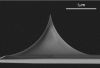
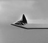
qp-HBC 
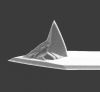
SEM image of qp-HBC AFM cantilever and AFM tip
This specific shape of that above-described heartbeat graph is a result of the snap-in-contact of the AFM tip while the AFM probe gets moved closer to the sample and then while the AFM probe gets moved away from the sample by the AFM system the snap-out-of-contact of the AFM tip and the forces and damping that the cantilever sees shortly after that last snap-out event.
Therefore, the right amount of damping plays an eminent role in the immediate and timely tapering of the amplitude after the AFM tip snaped-out-of-contact and until the next modulation cycle through the AFM system and ScanAsyst®** algorithm gets triggered.
In 2025 MikroMasch® has introduced the SelfAdjust-Air AFM probes with a sharp silicon tip on a silicon-based amorphous thin layer cantilever, designed specifically for the ScanAsyst® PeakForce Tapping™* mode application. MikroMasch® offer a step-by-step guide on how to use SelfAdjust-Air AFM probes in ScanAsyst®* mode on Bruker Nanoscope software.
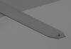
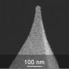
SelfAdjust-Air 
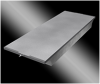
SEM image of MikroMasch® AFM Probe SelfAdjust-Air
The AFM cantilever damping itself is highly influenced by the shape of the AFM cantilever, especially the area of the AFM cantilever free end and naturally significantly by the AFM tip and AFM tip height itself, which determines how close the area of the free end of the AFM cantilevers gets to the sample surface. Huge variations in AFM tip height therefore results in huge variations in damping and are therefore counterproductive and should be avoided.
Additionally, and due to the fact that the ScanAsyst®** operation mode requires relatively soft AFM cantilevers the necessary coating for reflecting the laser beam for the AFM beam detection system could possibly lead to initial undesired bending of the AFM cantilevers and/or additionally AFM cantilever drift during AFM operation when the laser is placed onto the AFM cantilever and therefore the laser is heating up the AFM cantilever + applied metal sandwich layers – (adhesion layer + reflective layer => bi-metal-effect).
One way to reduce this above-mentioned AFM cantilever initial bending and drifting behavior during AFM operation is to only apply a partial reflex coating to the AFM cantilever beam instead of a full reflex coating covering the whole AFM body chip (AFM support chip) and also the full AFM cantilever beam. This sophisticated and work intensive partial coating technique of the AFM cantilevers beam reduces significantly initial bending especially for softer AFM cantilevers and also minimizes the drift of the AFM cantilever when exposed to the beam deflection laser or once immersed into fluids e.g. in the liquid cell.
With their flagship technology uniqprobe qp, NANOSENSORS™ are already utilizing such partial reflex coating techniques for some of their super soft AFM probe models. In the future this special technique certainly will be applied more widely and to more softer AFM cantilever types.
All AFM probes offered by us for this ScanAsyst®** mode are tested for a smooth and successful AFM operation.
Sort by:
9 results
best of the best

qp-HBC
uniqprobe™ - HeartBeat Cantilever for ScanAsyst®** and Peak Force Tapping™**
Coating:
Reflective Aluminum
Tip Shape: Circular symmetric
Tip Shape: Circular symmetric
AFM Cantilever:
F
60 kHz
C
0.5 N/m
L
115 µm
top value

SelfAdjust-Air
AFM probe for ScanAsyst®** mode in air
Coating:
Reflective Aluminum
Tip Shape: Rotated
Tip Shape: Rotated
AFM Cantilever:
F
70 kHz
C
0.4 N/m
L
100 µm
HQ:NSC19/Al BS
Standard Force Modulation AFM Probe
Coating:
Reflective Aluminum
Tip Shape: Rotated
Tip Shape: Rotated
AFM Cantilever:
F
65 kHz
C
0.5 N/m
L
125 µm

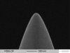
PNP-TRS
Silicon Nitride AFM Probe Single Cantilever Compatible with ScanAsyst®** Mode
Coating:
Reflective Gold
Tip Shape: Pyramid
Tip Shape: Pyramid
AFM Cantilever:
F
67 kHz
C
0.32 N/m
L
100 µm
HQ:NSC19/No Al
Standard Force Modulation AFM Probe
Coating:
none
Tip Shape: Rotated
Tip Shape: Rotated
AFM Cantilever:
F
65 kHz
C
0.5 N/m
L
125 µm
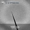
HiRes-C19/Cr-Au
High Resolution, Soft Tapping Mode AFM Probe
Coating:
Reflective Gold
Tip Shape: Supersharp
Tip Shape: Supersharp
AFM Cantilever:
F
65 kHz
C
0.5 N/m
L
125 µm
HQ:NSC19/Cr-Au
Gold Coated Force Modulation AFM Probe
Coating:
Gold Overall
Tip Shape: Rotated
Tip Shape: Rotated
AFM Cantilever:
F
65 kHz
C
0.5 N/m
L
125 µm
Mix and Match Box
Mixed box: up to 400 MikroMasch AFM probes
Coating:
various
Tip Shape: various
Tip Shape: various
NANOSENSORS™ Special Developments List (SDL)
Special AFM Probes etc. Showcasing NANOSENSORS™ Expertise
Coating:
various
Tip Shape: various
Tip Shape: various