This is a general step-by-step how-to-use instruction on how to optimize scan parameters on almost any AFM system, using almost any AFM probe.
Contact us if you need further information.
• Observe the Trace and Retrace height contours in the height channel.
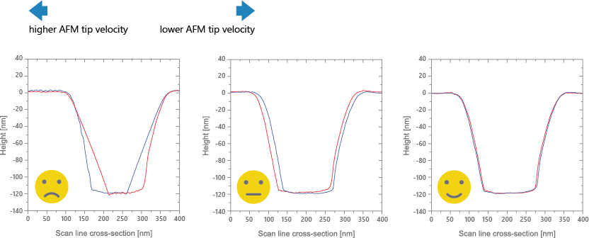
• If the Trace and Retrace lines do not follow each other closely, i.e. if they do not nearly overlap (left image), the AFM tip does not track the surface topography well. Reduce the AFM tip velocity gradually by reducing the Scan Rate or the Tip Velocity. Reducing the Scan Size also reduces the AFM tip velocity. Observe how the Trace and Retrace lines come closer together (middle image).
• When the AFM tip velocity is set properly, the AFM tip tracks the surface well; the Trace and Retrace lines follow each other closely (right image). A small offset between the two curves is acceptable.
• Reducing the AFM tip velocity further after this point increases unnecessarily the time to acquire a full AFM scan.

• Observe Trace and Retrace height contours in the height channel.
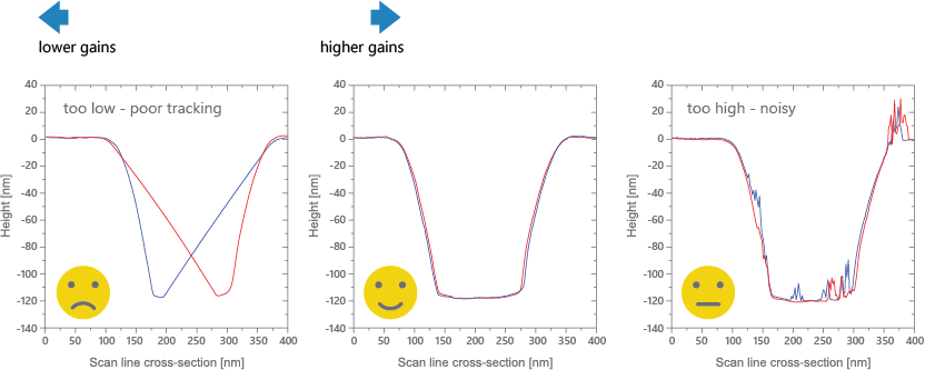
• If Trace and Retrace lines do not follow each other closely (left image), the AFM tip does not track the surface topography well. Increase the Proportional Gain and Integral Gain gradually and observe how the Trace and Retrace lines come closer together.
• When the Proportional Gain and the Integral Gain are set properly, the AFM tip tracks the surface well; the Trace and Retrace lines follow each other closely and there is no visible noise (middle image).
• Increasing the Proportional Gain and Integral Gain further after this point leads to ‘noise’ or spikes in the Trace and Retrace lines due to feedback oscillations (right image). If noise is visible in the Trace or Retrace lines, the gains are set too high. Reduce the Proportional Gain and the Integral Gain gradually and observe how the noise gets smaller and ideally disappears.

• Observe Trace and Retrace height contours in the hegith channel.
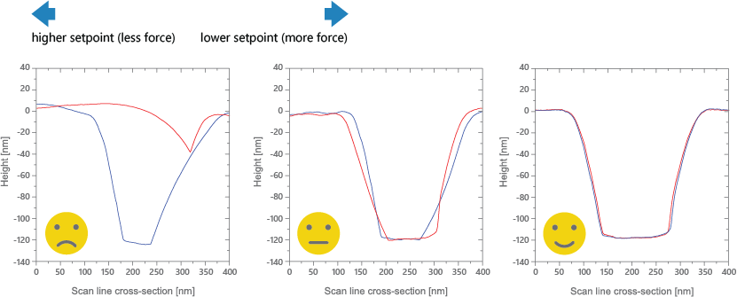
• If the Trace and Retrace lines do not follow each other closely (left image), the AFM tip does not track the surface topography well. Decrease the Setpoint gradually and observe how the Trace and Retrace lines come closer together (middle image).
• When the Setpoint is set properly, the AFM tip tracks the surface well; and the Trace and Retrace lines follow each other closely (right image).
• Reducing the Amplitude Setpoint further after this point increases AFM tip wear and reduces AFM tip life. Therefore, it is important to keep the Amplitude Setpoint at the highest value that still provides stable surface tracking.

